What is the modularization of design schematic diagram in Protel
Today, I will talk to you about the modularization of the design schematic in Protel, which may not be well understood by many people. in order to make you understand better, the editor has summarized the following content for you. I hope you can get something according to this article.
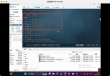
When designing the schematic diagram of a large system, there are usually many components, and the connections are complicated, so it is easy to make mistakes and look uncomfortable. if you systematize each module and classify the parts with different functions, then surround it with dotted frames of different colors, and then connect with buses of different colors. This not only looks beautiful, but also looks comfortable, and saves a lot of design time.
The following is about how to design.
For a simple schematic, see the instructions:
1. Power supply module
2.RS232 module
3.CAN bus module
4.MCU module
5.MCU Peripheral Crystal oscillator, reset, download Module
Separate these modules with different functions and circle them with PolyLine dotted lines for two purposes:
1. Separate one module from the other
two。 When designing later, just select the module along the dotted line and copy it to the new design schematic.
Assemble the various parts, like building blocks, copy whatever you want, then add the network number, connect to the bus, and a beautiful schematic diagram comes out.
After reading the above, do you have any further understanding of the modularization of design schematics in Protel? If you want to know more knowledge or related content, please follow the industry information channel, thank you for your support.